


Solar panel mount for trapezoidal profile metal roofs. The mount can be installed in two ways: in the valley of the profile directly to the batten with two screws, or on the crest of the profile with four screws. Installation to the batten gives more than twice the design load.
Technical data
| Parameter | To the batten (in the valley) | On the profile crest |
|---|---|---|
| Screws | 2 × roofing screw 6.5×40 mm with sealing washer | 4 × self-drilling screw 6.3×25 mm or 4 × roofing screw 6.5×40 mm, with sealing washer |
| Design pull-out load (perpendicular to the axis) | 6,00 kN | 2,60 kN |
| Design shear load (along the axis) | 8,00 kN | 4,10 kN |
| Distance between brackets | no more than 1100 mm | no more than 1100 mm |
Set contents
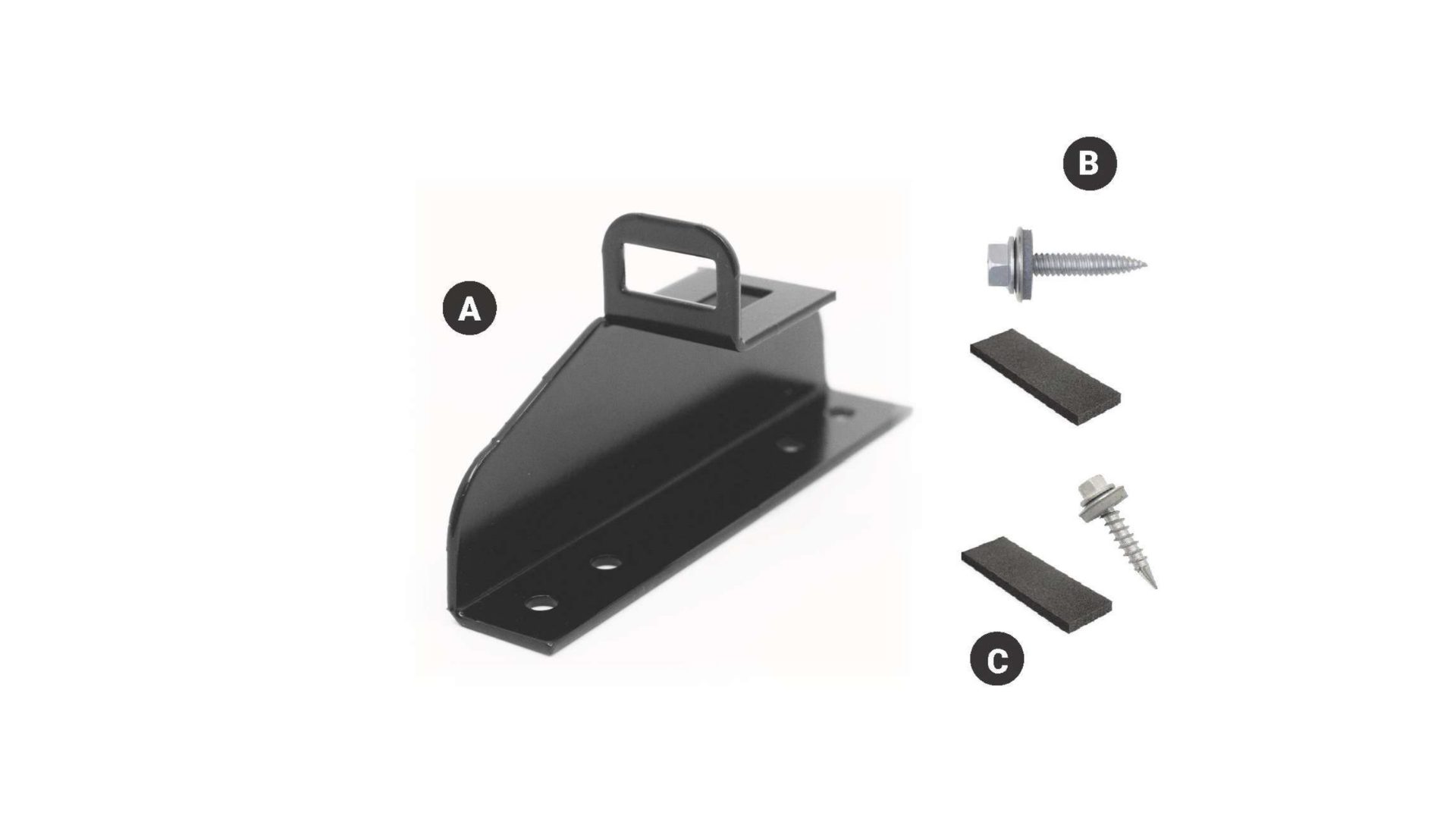
- A – solar panel mount
- B – self-drilling screw 6.3×25 mm with sealing washer, 4 pcs (for installation on the crest)
- C – roofing screw 6.5×40 mm with sealing washer, 2 pcs (for installation to the batten)
Installation on a trapezoidal profile roof
Choose the installation method
If there is a batten under the profile valley at the mount position, install to the batten – this is stronger. If there is no batten at that point, the mount is installed on the profile crest.
Screw the mount in place
On a batten: with 2 roofing screws 6.5×40 mm (C) through the sheet into the batten. On the crest: with 4 self-drilling screws 6.3×25 mm (B) or 4 roofing screws 6.5×40 mm.
Install the rails
The mounts are placed in a row at a spacing of up to 1100 mm, and the aluminium rails are screwed to their loops.
Important: do not tighten the screws in impact mode and do not overtighten them – the sealing washer must seat properly but must not be damaged.
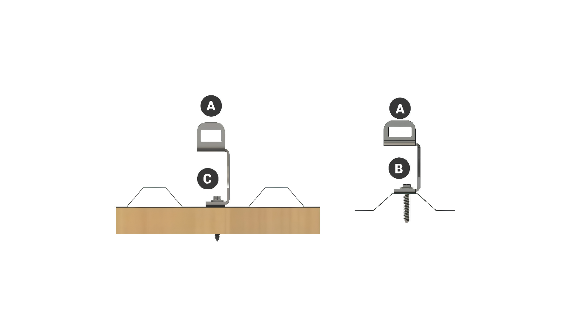
Left – installation in the profile valley to the batten (screws C). Right – installation on the profile crest (screws B).
Installing the rails
Aluminium rails are installed on the mounts, and the solar panels are then fixed to them. The rail is screwed to the mount loop with a T-bolt and nut. The rails and their connectors are not included in the mount set.
The manufacturer’s installation instructions specify:
- the first mount – no more than 300 mm from the end of the rail;
- distance between mounts – no more than 1100 mm;
- the rails are joined with a splice, and end caps are fitted at the rail ends;
- because of the thermal expansion of metal, the total length of rails joined in one row – no more than 15 m.
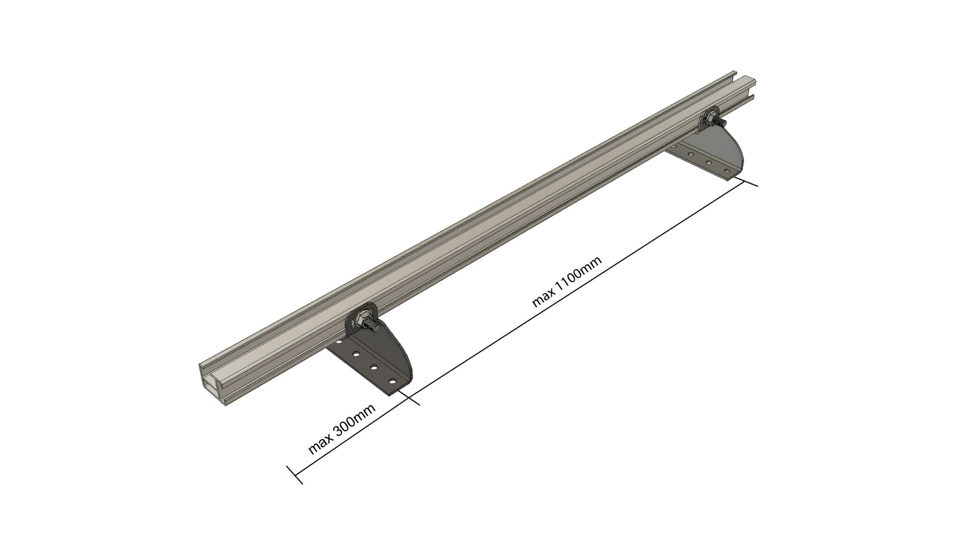
Mount spacing on the rail.
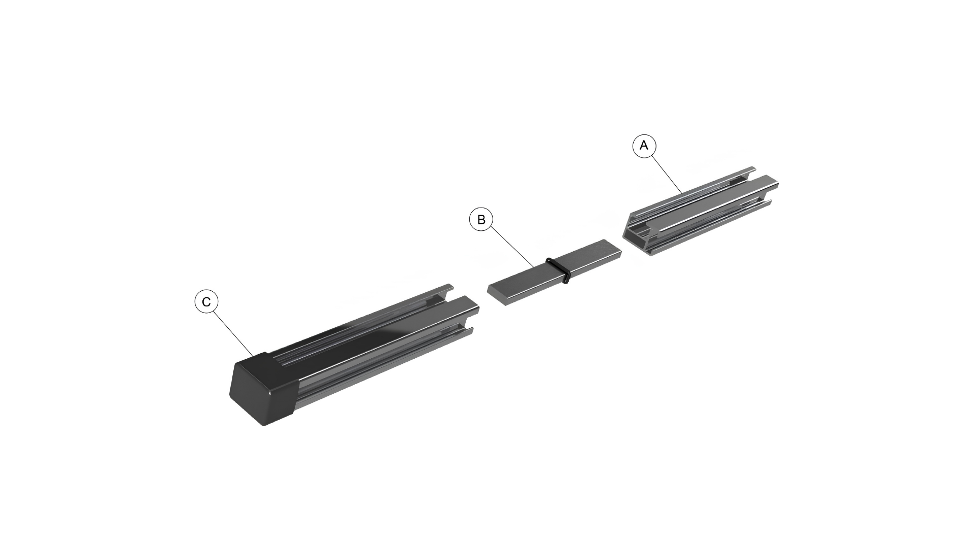
Joining the rails: A – aluminium rail, B – splice, C – end cap.
The number and position of mounts for a specific roof are determined by the solar panel system designer or installer, taking into account the weight of the panels and the wind and snow loads. If you use rails from another system, also follow the rail manufacturer’s instructions.
Which mount suits your roof?
Each metal roof profile has its own mount. All mounts are designed for aluminium rails, with a spacing of up to 1100 mm.
| Roofing | Fixing | Pull-out* | Shear* |
|---|---|---|---|
| Classic profile | on the seam with a counter plate, without drilling | 1,96 kN | 2,15 kN |
| Standing seam profile | on the standing seam with a counter plate, without drilling | 5,09 kN | 2,55 kN |
| Tile profile | to two battens, 2 screws with sealing washers | 6,00 kN | 7,00 kN |
| Trapezoidal profile (this page) | to the batten (2 screws) or on the crest (4 screws) | 6,00 / 2,60 kN | 8,00 / 4,10 kN |
* Design load per mount: pull-out – perpendicular to the mount axis, shear – along the axis. Trapezoidal profile: installation to the batten / on the profile crest.
Maintenance
The mounts will last a long time if they are installed according to the instructions and checked regularly:
- check the joints and the tightness of the screws;
- touch up any worn paint or galvanising with touch-up paint;
- replace mechanically damaged parts;
- regularly clear leaves, needles and other debris from around the mounts and under the panels.

